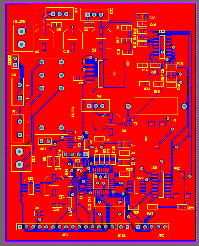


Then you put the decoupling cap on the other side between vias. Since you have a ground and power plane, just add a ground and power via to the corresponding pins of the opamp. Placement and routing of decoupling caps is really bad, long traces should be avoided. There is no need for an extra ground via.Ĭ1 and C2 should be C0G dielectric, do not use X7R. One pin on each photodiodes is connected to ground, so Altium will automatically connect this thru hole pad to the ground plane. Tiny 0402 SMD components are a hassle to hand solder, just use 0805. Print it at real size and put your arduino on top of the paper to make sure the pins align correctly. Just uncheck the "blind/buried" option, I think it's somewhere in the board stackup dialog. You don't need blind vias for this project, so make sure the board does not have them, otherwise the PCB fab will not be able to run it through the standard (cheap) process. These are much more expensive because they can't be manufactured just by drilling a hole through the whole board, more steps are needed, and these are special order, which means $$$. Your Altium stackup also mentions blind vias, which only connect 2 layers so they leave more space on the other layers. It will link all the layers where you connect a track to the via, and it will also connect to power/ground planes based on net names. When you use a standard thru via, it goes through all the layers. How can I send signals to the middle 2 layers in a 4 stack without the use of vias? Reply to layers is overkill, but these days it is pretty cheap and it saves time, so no problem with that.

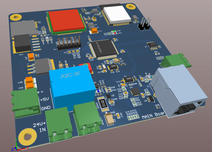
( Photodiode -> Transimpedance Op Amp -> 13-Bit ADC ) -> Arduino Micro -> PC Are there any evident improvements I can make to the schematic to improve the noise performance?.Are there any evident errors with the PCB layout?.This PCB is to be mounted on top of the Arduino Micro via the 17-pin headers, and will interface with the ADC using SPI protocol. My custom PCB consists of a photodiode, transimpedance op amp, 13-bit ADC, and bypass capacitors. I am very new to PCB design and have recently completed schematic capture and PCB layout of an optical detection circuit using Altium Designer.


 0 kommentar(er)
